First parts into the Paint Booth to get a light coating of AKZO after the Alumiprep & Alodine treatment.
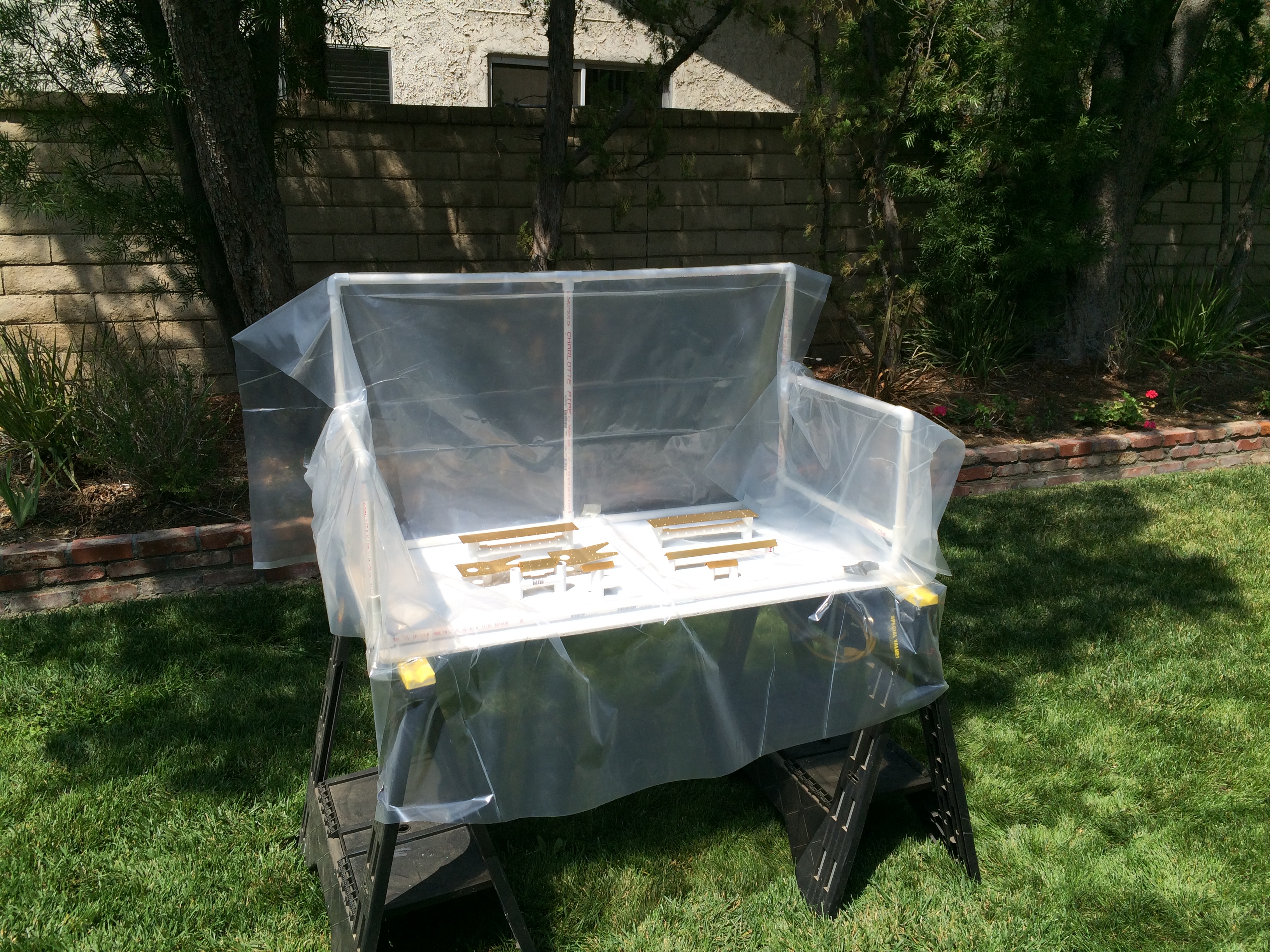

Tail assembly consisting of vertical stabilizer, rudder, horizontal stabilizer, and elevators.
First parts into the Paint Booth to get a light coating of AKZO after the Alumiprep & Alodine treatment.
Most of July was spent on my “day-job” at my Florida office. I did make time to attend 2016 Air Venture in Oshkosh (pics posted later).
Work resumed on Service Bulletin 14-01-31, (Cracking near the bend in horizontal stabilizer front spar), in late August.
 Step 1. Only applies to fully assembled aircraft.
Step 2. Remove the two most inboard rivets common between the HS-601PP Skins and the top and bottom flanges of the HS-702 Front Spar for both sides of the assembly.
Step 3. Remove the rivets attaching the HS-404 Nose Ribs and HS-405 Main Ribs to the skins.
Step 4. Remove the rivets holding the HS-404 Nose Ribs and HS-405 Main Ribs to the front and rear spars.
Step 5: Inspect the HS-405 Main Ribs removed in Step 4 for cracks.
 Step 6: Remove the rivets holding the HS-710 Reinf. Angle to the front spar. Remove the angle and double check that the corners of the fwd facing flange have been relieved.
Step 7: Remove the rivets holding the HS-714 Splice Angle to the front spar.
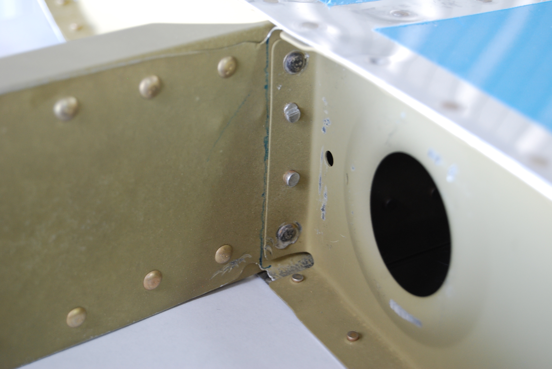
Step 8: Inspect the corners at the inboard end of the top and bottom fwd spar flanges on the left and right spar halves for the presence of relief notches
Step 9: Carefully inspect any detected cracks for length and termination point – N/A my aircraft has flown yet.
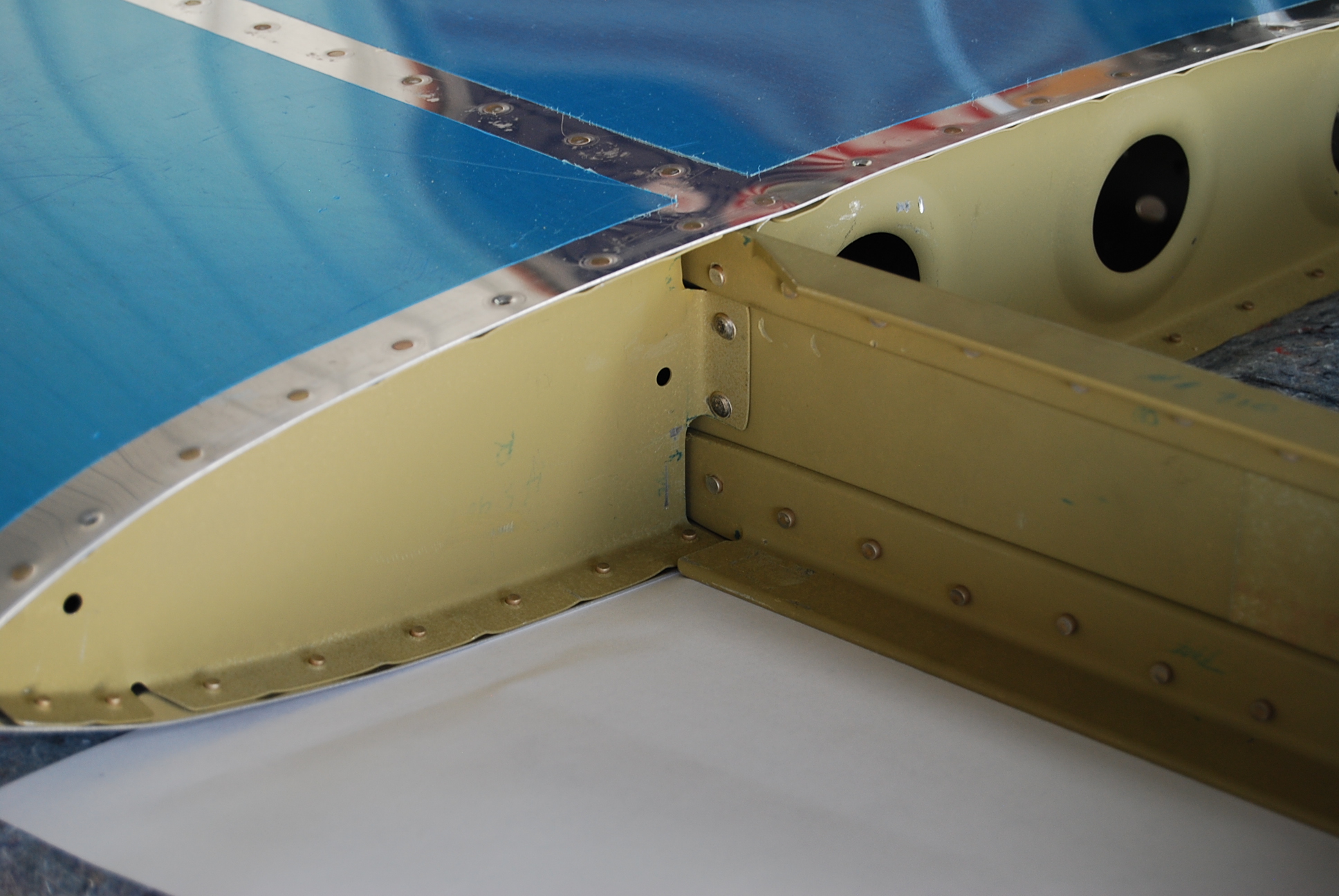
Step 10: Trim the upper and lower inboard flanges of the Front Spar. (Insert a piece of stainless steel sheet scrap between the skin and the flange of the front spar to protect the skin from damage while trimming.) Radius and deburr as well as possible, the cut edge of the spar flange. We have obtained good results using a Dremel™ style tool with a thin abrasive cutting disk, to make the cut.

Step 11: Radius the outboard forward “cut” edge
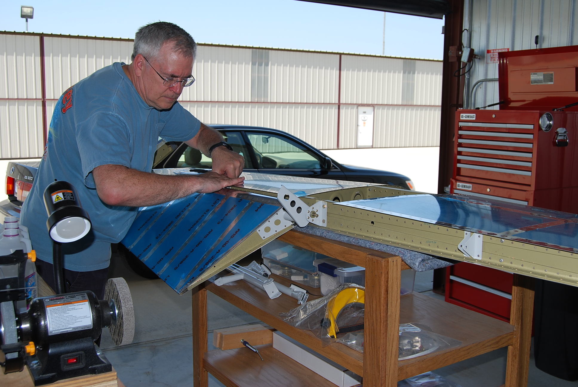
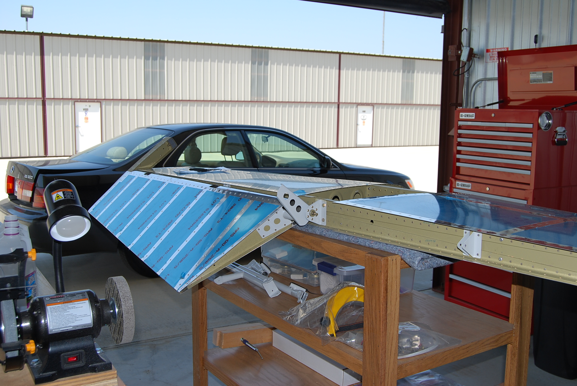
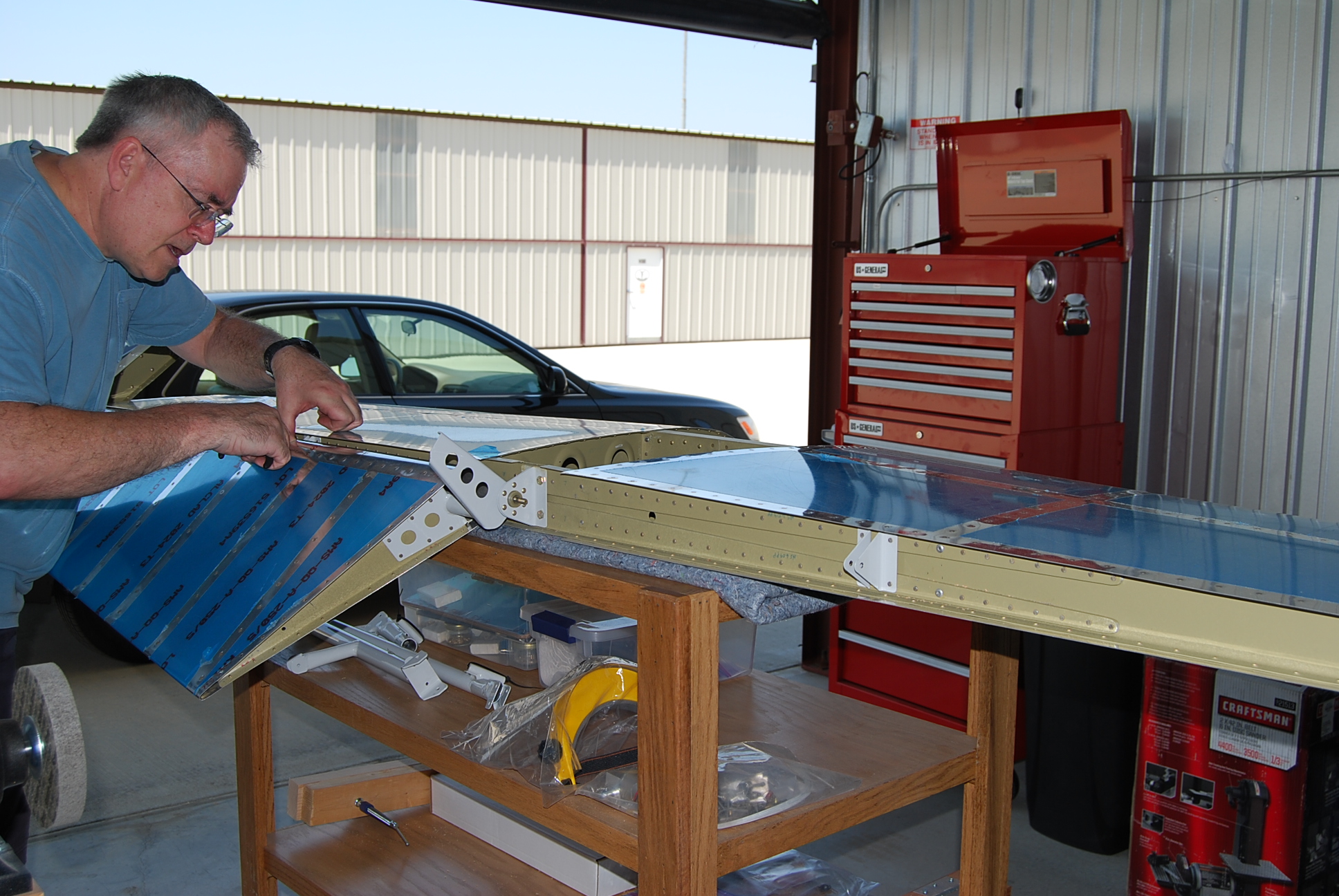
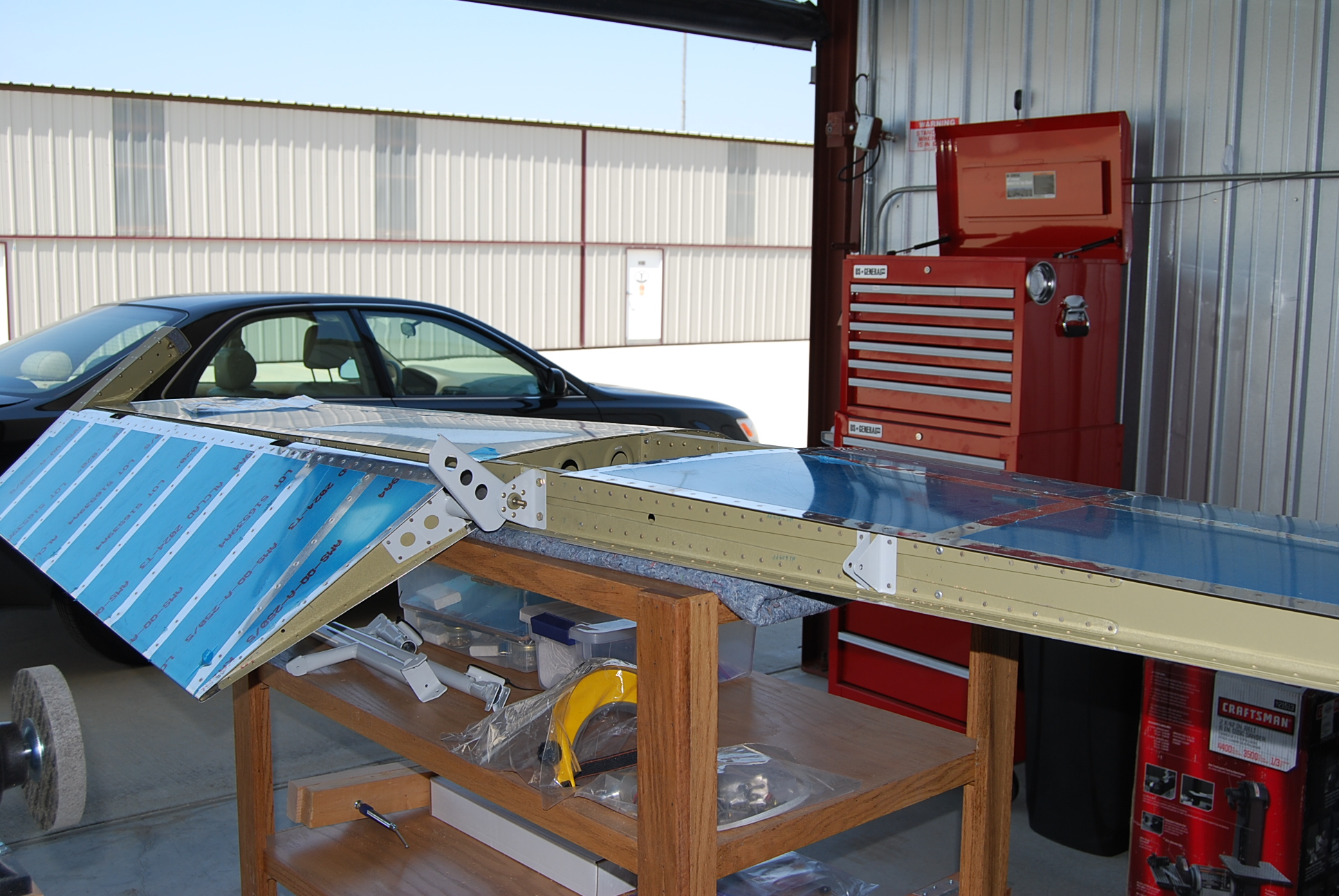
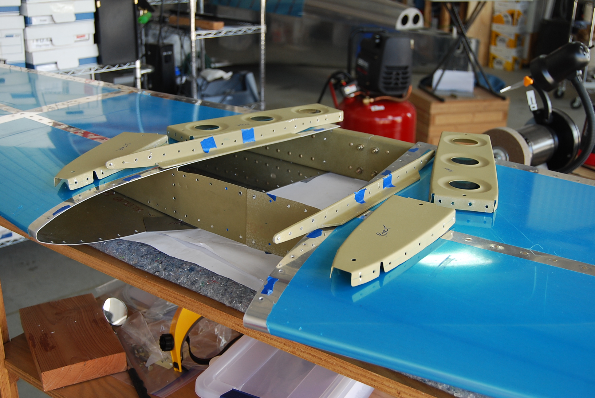
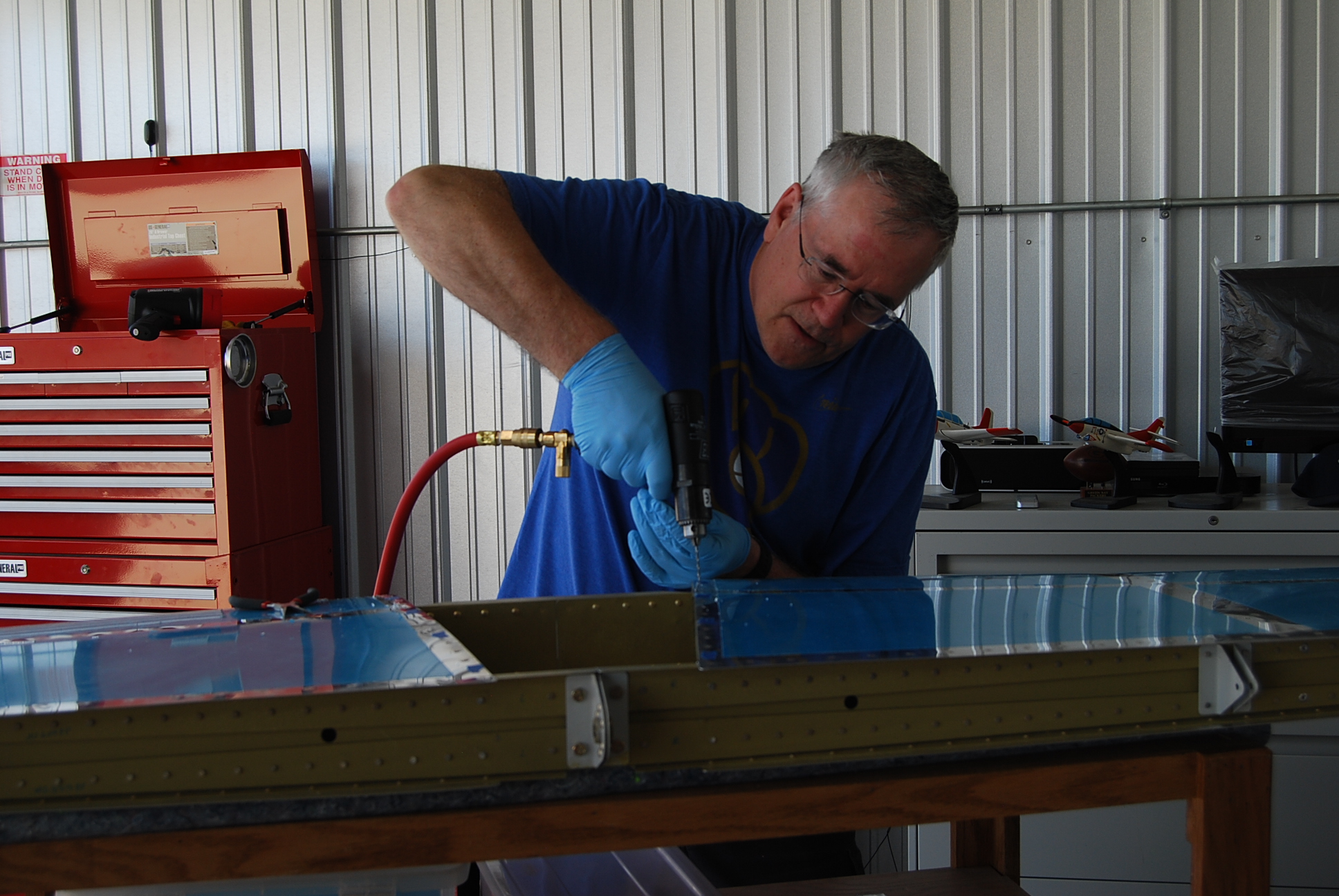 Starting the process of drilling out the AN426 flush head rivets holding the skins to the inner horizontal stabilizer ribs.
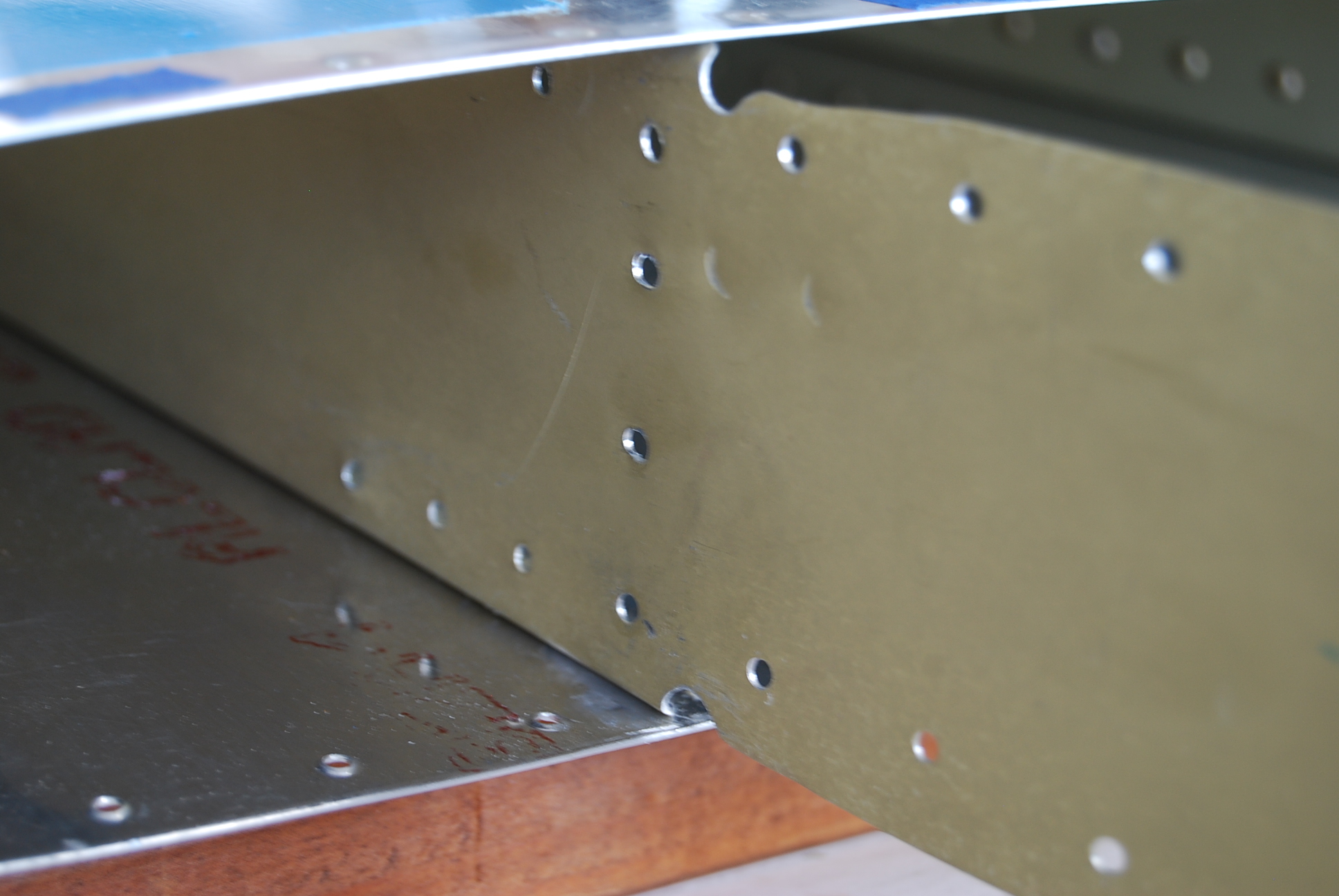
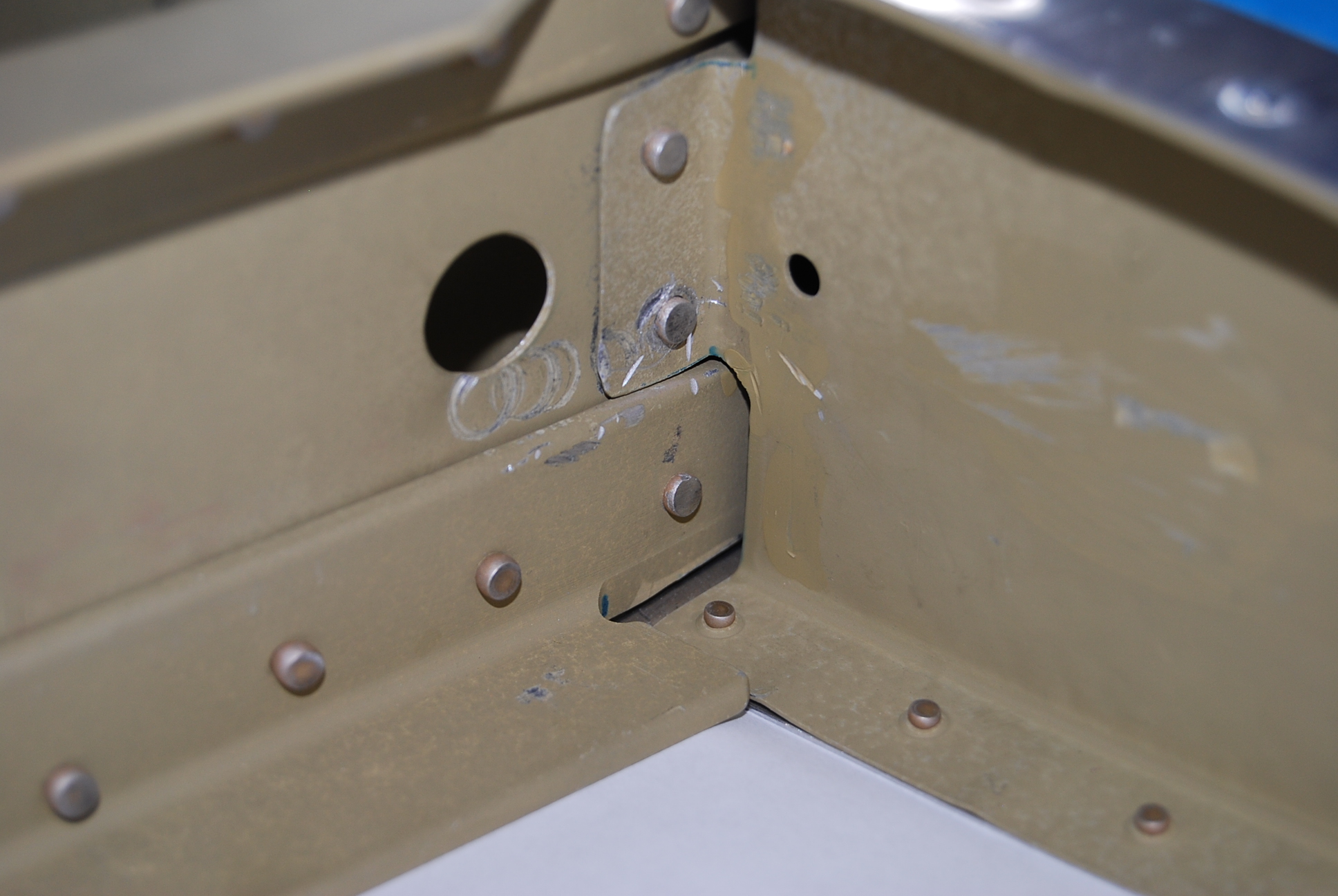
Closer inspection of the affected area. Inspection shows rivet gun and pneumatic drill tool marks.

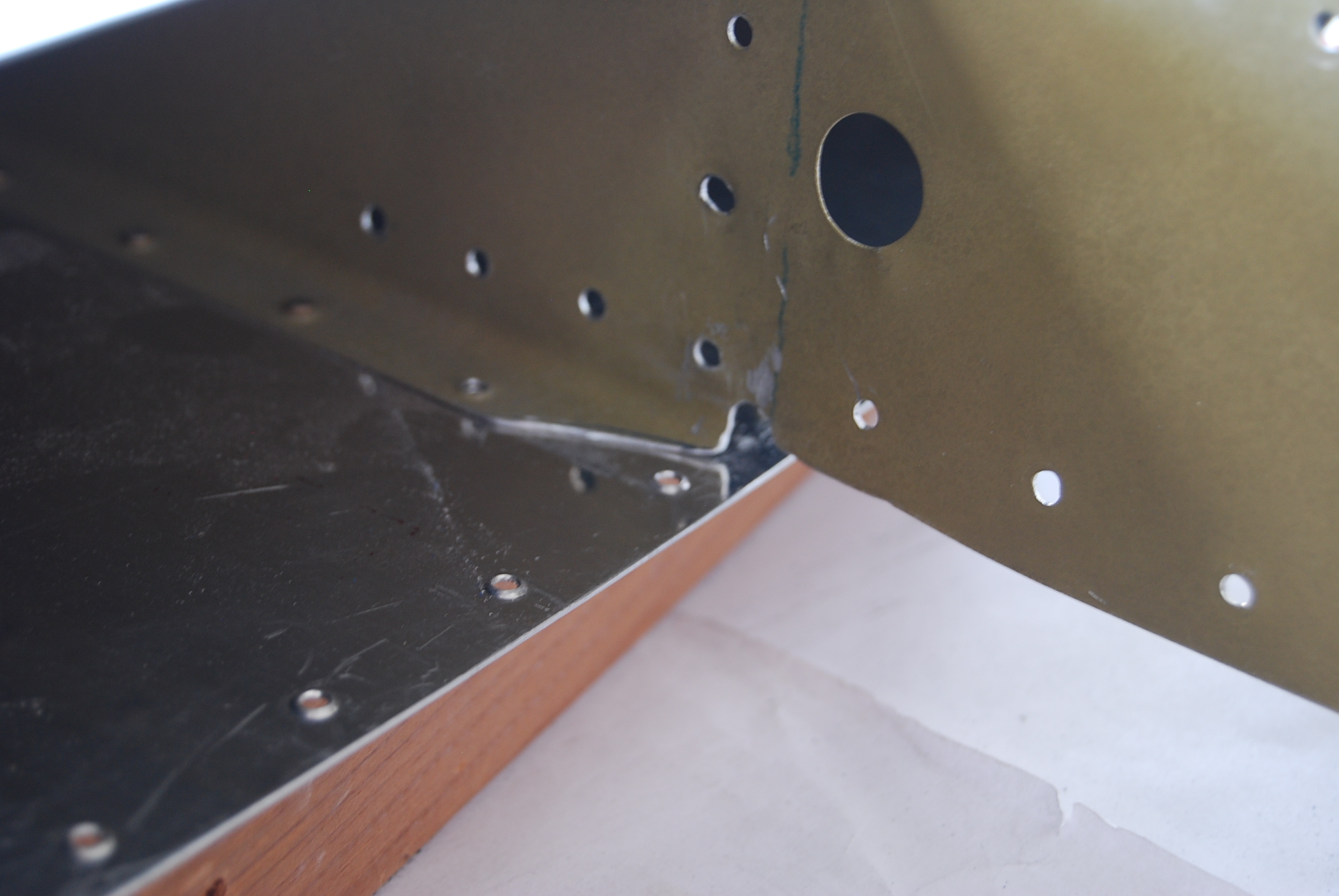
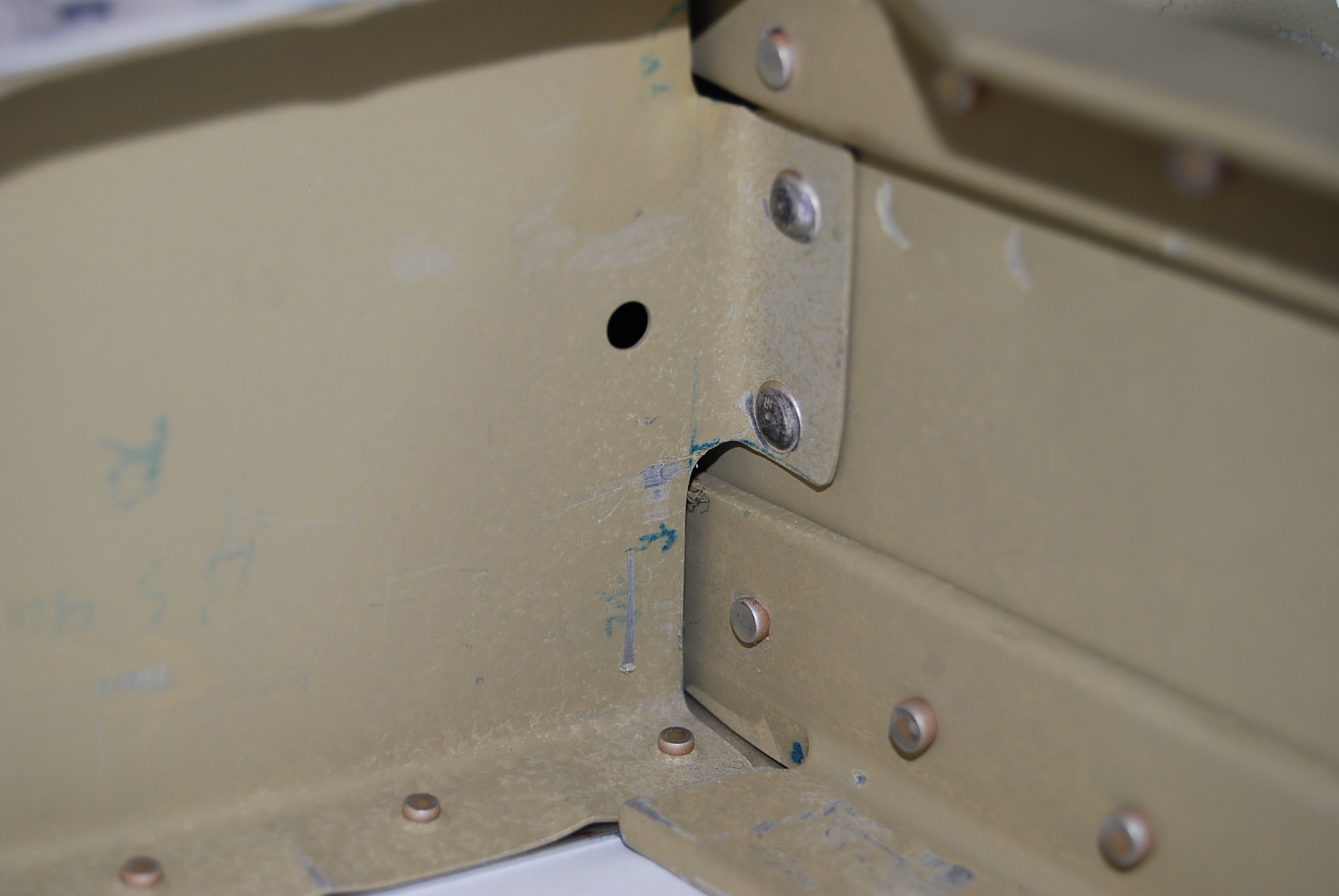
 This picture shows a problem area that a stress crack would probably form. The rough corner needs to have an acceptable radius replace the ragged edge.
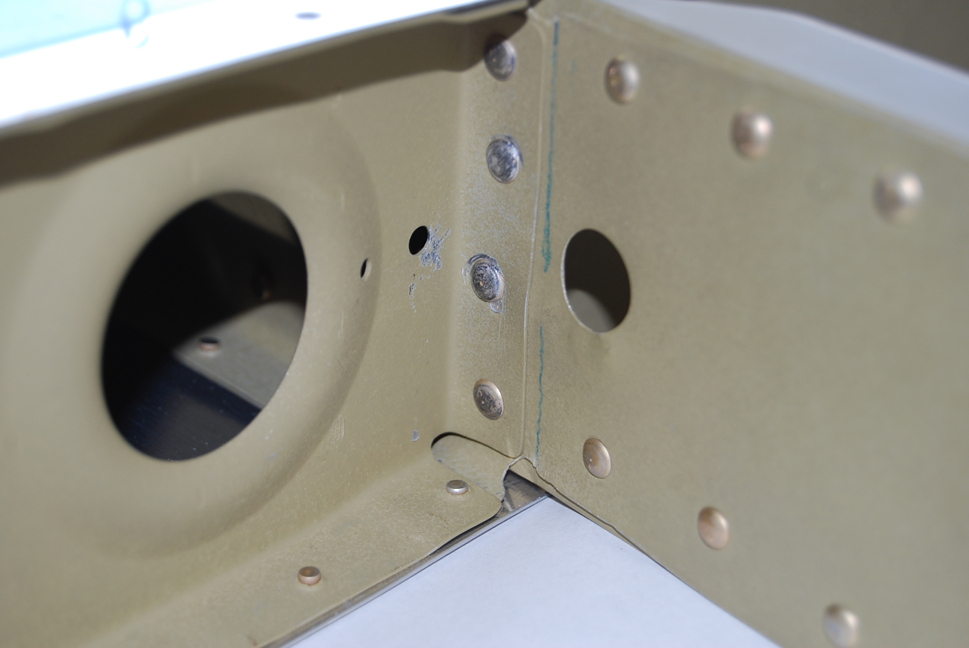
Removed the elevators from the horizontal stabilizer to start the Service Bulletin (SB14-01-31) to correct a horizontal front spar cracking issue.